
A minimal x86 bootloader from scratch
← back to blogBuilding a Bootloader from Scratch: A Deep Dive into x86 Boot Process

So you want to understand how computers actually boot? Not the handwavy “BIOS loads the OS” explanation, but the real, low-level mechanics of what happens when you hit the power button? Good
This project is a minimal but complete bootloader that takes you from the moment the CPU starts executing at power-on, through loading code from disk, setting up memory segmentation, switching processor modes, and finally running C code. It’s about 100 lines of assembly and 5 lines of C .
The Problem We’re Solving
Modern operating systems are complicated beasts. Linux is millions of lines of code. Windows is even more. But they all start the same way: with 512 bytes of code loaded by the BIOS at a specific memory address. That’s it
Those 512 bytes need to:
- Set up a working environment
- Load more code from disk (because 512 bytes isn’t enough for anything useful)
- Switch the CPU from 1981 compatibility mode into something resembling modern computing
- Transfer control to your actual operating system
The bootloader presented here is the smallest practical path from power-on to executing C code. It relies solely on handwritten x86 assembly interacting directly with the CPU and BIOS, deliberately avoiding any external boot infrastructure.
WHY

Most modern development never gets anywhere near this layer, and the system is usually content to keep its earliest steps politely out of sight. Still, understanding those first instructions changes how the rest of the stack makes sense.
Working at this level forces you to confront how memory behaves in physical terms. Not heap allocators and convenient abstractions, but real addresses, segmentation rules, and the structures that determine how the processor interprets space.
It also replaces the idea of a “virtual” machine with the one that actually exists.
The Boot Process: What Actually Happens
Power On
When you press the power button, here’s what happens:
- Power supply stabilizes - Takes a few milliseconds
- CPU reset line goes high - CPU starts executing
- CPU jumps to firmware - On x86, this is address
0xFFFFFFF0(yes, near the top of the 32-bit address space) - BIOS/UEFI runs - Checks hardware, runs POST (Power-On Self Test)
- BIOS looks for boot device - Checks floppy, hard drive, CD-ROM, USB, network, whatever boot order you set
- BIOS reads first sector - Takes 512 bytes from sector 0 of the boot device
- BIOS checks magic number - Last two bytes must be
0x55 0xAA(little-endian for0xAA55) - If valid, BIOS loads it to 0x7C00 - This address is hardcoded in the BIOS
- BIOS jumps to 0x7C00 - Your code is now running!
At this point, you’re executing in 16-bit real mode, you have access to BIOS interrupts, and you have 512 bytes to do something useful.
Why 0x7C00?

This is one of those historical quirks. The original IBM PC had 32KB of RAM. The BIOS used the first section for its data structures and interrupt vectors. The boot sector needed to be high enough to not conflict with BIOS data, but low enough to leave space for the boot program to set up a stack.
Someone at IBM decided on 0x7C00 and now, 40+ years later, we’re still using it. Every x86 CPU boots the same way. Backward compatibility is a hell of a drug.
Why 512 Bytes?
Because that’s how big a disk sector is. Or rather, that’s how big disk sectors were on floppy disks in 1981. The BIOS reads one sector, and one sector is 512 bytes. Modern drives use larger sectors (often 4KB), but they emulate 512-byte sectors for compatibility.
That 0xAA55 magic number in the last two bytes is how the BIOS knows you’re actually a boot sector and not just random data that happened to be on the disk.
The Master Boot Record
Let’s look at master_boot_record.asm line by line:
[bits 16]This tells NASM (the assembler) to generate 16-bit code. When the CPU starts, it’s in real mode, which is the 16-bit mode that the original 8086 had in 1978. Even modern 64-bit CPUs start in this mode for compatibility.
org 0x7c00This is imp. The org directive tells the assembler “assume this code will be loaded at address 0x7c00”. Without this, all your memory references would be wrong. If you write jmp label, the assembler needs to know where label will actually be in memory. It calculates offsets based on the org address.
Kernel_offset equ 0x1000We’re going to load our kernel to address 0x1000 (4KB). Why there? Because it’s far enough from our bootloader (which ends at 0x7e00) and far enough from the BIOS data area (which ends around 0x500). There’s nothing scientific about 0x1000 - it’s just a nice round number in the free region.
mov [BOOT_DRIVE], dlWhen the BIOS jumps to your code, it puts the boot drive number in the dl register. 0x00 for the first floppy, 0x80 for the first hard drive, etc. We save this immediately because we’ll need it later to read more sectors from the same drive.
mov bp, 0x900
mov sp, bp
Setting up the stack. The stack grows downward, so we set the base pointer (bp) and stack pointer (sp) to 0x900. This gives us a stack from 0x900 down to wherever the BIOS data ends (around 0x500). That’s about 1KB of stack space, which is plenty for our bootloader.
Why 0x900? Again, it’s in the free region. Below our code at 0x7c00, above the BIOS data. Could be 0x800 or 0xa00 - doesn’t really matter as long as it doesn’t overlap with anything else.
call load_kernel
call switch_2_32bit
Here’s where we do the actual work. First, load more code from disk. Second, switch to 32-bit mode.
jmp $“Jump to current address” - an infinite loop. If we get here, something went wrong. This prevents the CPU from running off into random memory and executing garbage as instructions.
%include "disk.asm"
%include "gdt.asm"
%include "switch2_32bit.asm"
NASM literally copy-pastes these files here. It’s not like C includes - there’s no separate compilation. The assembler just reads these files and inserts their contents at this point.
[bits 16]

load_kernel:
    mov bx, Kernel_offset
    mov dh, 2
    mov dl, [BOOT_DRIVE]
    call disk_load
    ret
This sets up the parameters for disk_load and calls it. We want to load 2 sectors (dh = 2) from the boot drive to address 0x1000 (bx = Kernel_offset). Why 2 sectors? Because our kernel is small. If it were bigger, we’d load more.
[bits 32]

BEGIN_32BIT:
    call Kernel_offset
    jmp $
This code runs after we’ve switched to 32-bit mode. Note the [bits 32] directive - now we’re generating 32-bit instructions. We call the kernel (which is now loaded at 0x1000), and if it ever returns (it shouldn’t), we loop forever.
BOOT_DRIVE db 0Storage for the boot drive number. db means “define byte” - reserve one byte of space, initialized to 0.
times 510 - ($-$$) db 0This is some assembler stuff. $ is the current address, $$ is the start of the section. So ($-$$) is how many bytes we’ve used so far. 510 - ($-$$) is how many bytes we have left (out of 512 total, minus 2 for the magic number). times repeats the following instruction that many times. So this pads with zeros until we reach byte 510.
dw 0xaa55The magic number. dw means “define word” (2 bytes). This writes 0x55 0xaa (little-endian) at bytes 510-511. The BIOS checks for this and won’t boot if it’s not there.
Deep Dive: Reading From Disk
CPU Registers x86 - CR0 Documentation
The disk.asm file uses BIOS interrupt 0x13 to read sectors from disk. Interrupts are the way you communicate with the BIOS in real mode. You set up registers with parameters, call int 0x13, and the BIOS does the work.
disk_load:
    pusha
    push dx
Save all registers. BIOS interrupts might clobber them, and we want to restore the state afterward. pusha pushes all general-purpose registers at once.
mov ah, 0x02Function 0x02 of interrupt 0x13 is “read sectors”. The function number goes in ah. Different values of ah do different things (0x00 resets the disk controller, 0x03 writes sectors, etc.).
mov al, dhNumber of sectors to read. We put this in dh before calling, now move it to al where the BIOS expects it.
mov cl, 0x02Start reading from sector 2. Sector numbers start at 1 (not 0, because of course they don’t). Sector 1 is our boot sector, so sector 2 is where our kernel starts.
mov ch, 0x00
mov dh, 0x00
Cylinder 0, head 0. On modern drives, these don’t really correspond to physical geometry anymore, but the BIOS interface still uses this CHS (Cylinder-Head-Sector) addressing. For small bootloaders, we can just use cylinder 0, head 0 and increment sectors.
int 0x13Call the BIOS. This actually reads from the disk into memory at es:bx. We have bx set to our kernel offset, and es defaults to 0, so we’re reading to 0x0000:0x1000 which is just 0x1000.
jc disk_errorJump if carry flag is set. The BIOS sets the carry flag if an error occurred. We’d jump to an error handler (which in our case is just an infinite loop).
pop dx
cmp al, dh
jne sector_error
The BIOS returns the number of sectors actually read in al. We compare it to how many we expected (dh, which we saved on the stack). If they don’t match, something went wrong.
popa
ret
Restore registers and return. If u made it here, the kernel is loaded into memory.
The Global Descriptor Table
Before we can switch to protected mode, we need to set up the GDT..
Memory Segmentation: Why?

Global Descriptor Table - Wikipedia
Segment Descriptor - Wikipedia
In real mode, memory addresses work like this: segment:offset. You have a 16-bit segment register and a 16-bit offset. The actual physical address is (segment << 4) + offset. This lets you address 1MB of memory (20 bits) with 16-bit registers.
In protected mode, segments work differently. Instead of shifting and adding, the segment register contains an index into the GDT. Each GDT entry describes a segment: base address, limit, access rights, privilege level.
This gives you:
- Memory protection - Segments can be marked as read-only, executable, etc.
- Privilege levels - Ring 0 (kernel) vs Ring 3 (user programs)
- More address space - Base can be 32-bit, limit can be up to 4GB
For our simple bootloader, we’re going to set up flat segmentation: one code segment and one data segment, both covering the entire 4GB address space. This is what modern OSes do - real segmentation is basically unused on x86-64. We set it up because the CPU requires it, then ignore it and use paging instead.
GDT Structure
gdt_start:
    dq 0x0
The first entry must be null. This is a requirement. Any attempt to load a segment register with 0 will cause a fault. It’s a safety feature - if you accidentally use an uninitialized segment register, you get a clear error instead of random behavior.
gdt_code:
    dw 0xffff    ; Segment limit, bits 0-15
    dw 0x0       ; Base address, bits 0-15
    db 0x0       ; Base address, bits 16-23
    db 10011010b ; Access byte
    db 11001111b ; Flags and limit bits 16-19
    db 0x0       ; Base address, bits 24-31
A GDT entry is 8 bytes. The layout is weird because of historical reasons (the original 80286 had a different format, and they extended it for 32-bit while keeping backward compatibility). Let’s break down that access byte:
10011010b
│││││││└─ Accessed bit (CPU sets this when segment is accessed)
││││││└── Readable (for code) / Writable (for data)
│││││└─── Executable (1 = code segment, 0 = data segment)
││││└──── Must be 1
│││└───── Privilege level (0-3, we use 0 for kernel)
││└────── Privilege level
300: │└─────── Present bit (must be 1)
So 10011010b means: present, privilege 0, must-be-1, executable, readable, not accessed yet.
The flags byte is split:
11001111b
││││└┴┴┴─ Limit bits 16-19
│││└───── Available for OS use
││└────── Must be 0 (for 32-bit segments)
│└─────── Size (1 = 32-bit, 0 = 16-bit)
└──────── Granularity (1 = limit is in 4KB blocks)
So 11001111b means: granularity=1 (4KB blocks), 32-bit, limit bits are all 1. With granularity set and limit=0xfffff, this gives us a 4GB segment (0xfffff * 4KB = 4GB).
The data segment is similar, just with 10010010b as the access byte (not executable, writable).
gdt_descriptor:
    dw gdt_end - gdt_start - 1
    dd gdt_start
This is the GDT descriptor that we load with lgdt. It’s 6 bytes: 2-byte size (total bytes minus 1), 4-byte address of the GDT. The CPU needs this to know where the GDT is and how big it is.
CODE_SEG equ gdt_code - gdt_start
DATA_SEG equ gdt_data - gdt_start
These calculate offsets to our segments. CODE_SEG is 8 (first entry after null), DATA_SEG is 16. These are segment selectors - when we load CODE_SEG into a segment register, the CPU looks at GDT entry 8.
Switching to Protected Mode

This is the climax ehe . We’re going to flip one bit in a control register, and the CPU will completely change how it operates.
[bits 16]

switch_2_32bit:
    cli
Clear interrupts. BIOS interrupts don’t work in protected mode, and we haven’t set up our own interrupt handlers yet. If an interrupt fires during the transition, bad things happen. So we disable them.
lgdt [gdt_descriptor]Load the GDT. This tells the CPU “here’s your new segmentation table”. The CPU doesn’t start using it yet - we’re still in real mode - but it needs to be loaded before we switch.
mov eax, cr0
or eax, 0x1
mov cr0, eax
Here it is. Control register 0 has a bunch of flags. Bit 0 is PE (Protection Enable). Setting it switches the CPU to protected mode. We read CR0, set bit 0, write it back. The instant that mov cr0, eax executes, we’re in 32-bit protected mode.
jmp CODE_SEG:init_32bitThis is a far jump. It does two things:
- Loads
CS(code segment) withCODE_SEG, making the CPU actually start using our GDT - Flushes the instruction pipeline
The CPU prefetches instructions. Right now the pipeline has 16-bit instructions that were fetched before we switched modes. If we kept executing, we’d be trying to execute 16-bit instructions in 32-bit mode. This causes instant crashes. The far jump clears the pipeline and forces the CPU to refetch from the new address, now interpreting everything as 32-bit code.
[bits 32]

init_32bit:
    mov ax, DATA_SEG
    mov ds, ax
    mov ss, ax
    mov es, ax
    mov fs, ax
    mov gs, ax
Load all segment registers with our data segment. In protected mode, you can’t use segments that aren’t in the GDT. We load them all with DATA_SEG so memory accesses work correctly.
mov ebp, 0x90000
mov esp, ebp
Set up a new stack. We use 0x90000 (576KB) which is well into extended memory. We need a bigger stack now because we might be doing more complex things. The old stack was in the first 1MB, which is fine but cramped.
call BEGIN_32BITJump back to the MBR, which has a BEGIN_32BIT label that calls our kernel. We’ve made it. We’re running 32-bit code.
The Kernel
void main() {
    char* video = (char*) 0xb8000;
    *video = 'X';
}
This is possibly the simplest kernel in existence.
0xb8000 is the start of VGA text mode video memory. In text mode (which is what the BIOS sets up), the screen is 80x25 characters. Each character takes 2 bytes: one for the ASCII code, one for the attribute (color).
By writing 'X' to 0xb8000, we put ‘X’ in the top-left corner of the screen. The default color is light gray on black, so you’ll see a light gray X.
If you wanted to make it red:
char* video = (char*) 0xb8000;
*video = 'X';
*(video + 1) = 0x04;  // Red on black
The attribute byte is 0x04 for red foreground, black background. The low nibble is foreground, high nibble is background.
To write a string:
char* video = (char*) 0xb8000;
char* message = "Hello, World!";
int i = 0;
while (message[i] != 0) {
    video[i*2] = message[i];
    video[i*2 + 1] = 0x0F;  // White on black
    i++;
}
No printf. No standard library. Just raw memory writes. That’s what “freestanding” means - no hosted environment, no runtime support. Just you and the hardware.
The Memory Map: Where Everything Lives
Here’s what our memory looks like after loading:
0x00000 - 0x003FF   Real Mode IVT (Interrupt Vector Table) - unused in protected mode
0x00400 - 0x004FF   BIOS Data Area
0x00500 - 0x006FF   Free (can use for bootloader data)
0x00700 - 0x008FF   Free
0x00900 - 0x00900   Our bootloader stack (grows down from here)
0x007C00 - 0x007DFF Our MBR (loaded by BIOS)
0x007E00 - 0x00FFF  Free
0x01000 - 0x01FFF   Our kernel (loaded by MBR)
0x02000 - 0x7FFFF   Free (conventional memory)
0x80000 - 0x9FFFF   Extended memory (free)
0xA0000 - 0xBFFFF   Video memory
0xC0000 - 0xFFFFF   BIOS ROM
The first megabyte is called conventional memory. Above that is extended memory, which requires protected mode to access. That’s one reason we switch to protected mode - we want all 4GB of address space, not just 1MB.
Building This Thing
The Makefile orchestrates the build:
-
Assemble the MBR:
nasm -f bin master_boot_record.asm -o master_boot_record.bin-f binmeans output raw binary (not an object file)- This produces exactly 512 bytes
-
Compile the kernel:
gcc -m32 -ffreestanding -fno-pie -c kernel.c -o kernel.o-m32targets 32-bit x86-ffreestandingsays we’re not hosted (no libc)-fno-piedisables position-independent code-ccompiles but doesn’t link
-
Link the kernel:
ld -m elf_i386 -Ttext 0x1000 --oformat binary kernel.o -o kernel.bin-Ttext 0x1000means “put the code at address 0x1000”--oformat binaryoutputs raw binary (not ELF)- This strips all the ELF headers - we just want machine code
-
Concatenate:
cat master_boot_record.bin kernel.bin > os-image.bin- This creates a disk image: 512 bytes of MBR, then kernel
- When BIOS loads sector 1, it gets the MBR
- When the MBR loads sector 2+, it gets the kernel
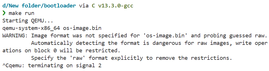
The final os-image.bin is what you’d write to a USB drive or floppy disk to make a bootable device. QEMU can boot from it directly.
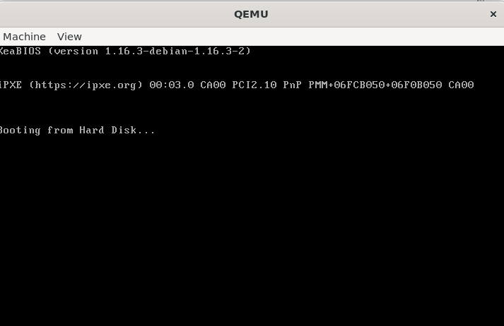
Running and Testing
make runThis fires up QEMU with your image. You should see a black screen with a single ‘X’ in the top-left corner. That’s your operating system.
A Note on Modern Systems
Everything in this document assumes legacy BIOS boot. Modern systems use UEFI, which is completely different:
- No 16-bit real mode
- PE32+ executables instead of raw binary
- FAT filesystem required
- Boot services API instead of BIOS interrupts
- Secure Boot signature verification
UEFI is technically superior - better architecture, more features, no 40-year-old cruft. But it’s also more complex and less educational. Legacy BIOS boot teaches you what’s actually happening at the CPU level. UEFI hides that behind abstraction layers.
Most computers still support “Legacy Boot” or “CSM” (Compatibility Support Module) mode. Enable that in BIOS settings if you want to test this bootloader on real hardware.
For learning, start with BIOS. Understand the fundamentals. Then tackle UEFI when you know what problems it’s solving.
Final Thoughts
You’ve written code that runs on bare metal, with no OS underneath. You’ve talked directly to the CPU, set up memory segmentation, switched processor modes. This is as low-level as programming gets (well, except for writing microcode or designing CPUs, but that’s a different kind of low-level).
Appendix: Quick Reference
NASM Directives
org 0x7c00          ; Set origin address
bits 16             ; Generate 16-bit code
bits 32             ; Generate 32-bit code
%include "file.asm" ; Include another file
db 0x00             ; Define byte
dw 0x0000           ; Define word (2 bytes)
dd 0x00000000       ; Define double word (4 bytes)
dq 0x0000000000000000 ; Define quad word (8 bytes)
times 10 db 0       ; Repeat instruction 10 times
$                   ; Current address
$$                  ; Section start address
equ                 ; Define constant
x86 Registers (32-bit)
EAX, EBX, ECX, EDX  ; General purpose
ESI, EDI            ; Source/Destination index
EBP, ESP            ; Base/Stack pointer
EIP                 ; Instruction pointer
CS, DS, ES, FS, GS, SS ; Segment registers
CR0, CR2, CR3, CR4  ; Control registers
Common Instructions
mov dest, src       ; Move data
add dest, src       ; Add
sub dest, src       ; Subtract
and dest, src       ; Bitwise AND
or dest, src        ; Bitwise OR
xor dest, src       ; Bitwise XOR
push src            ; Push onto stack
pop dest            ; Pop from stack
call label          ; Call function
ret                 ; Return from function
jmp label           ; Unconditional jump
je label            ; Jump if equal
jne label           ; Jump if not equal
jc label            ; Jump if carry
jnc label           ; Jump if not carry
cmp op1, op2        ; Compare (sets flags)
int 0x13            ; Software interrupt
cli                 ; Clear interrupts
sti                 ; Set interrupts
lgdt [address]      ; Load GDT
BIOS Interrupts (Real Mode Only)
int 0x10            ; Video services
  ah=0x00           ; Set video mode
  ah=0x0e           ; Teletype output (print char)

int 0x13            ; Disk services
  ah=0x00           ; Reset disk controller
  ah=0x02           ; Read sectors
  ah=0x03           ; Write sectors

int 0x16            ; Keyboard services
  ah=0x00           ; Read keystroke
  ah=0x01           ; Check for keystroke
Useful Memory Addresses
0x7C00              ; Boot sector load address
0xB8000             ; VGA text mode video memory
0x0000-0x03FF       ; Real mode IVT
0x0400-0x04FF       ; BIOS data area
GDT Access Byte Format
Bit 7: Present (must be 1)
Bit 6-5: Privilege level (0=kernel, 3=user)
Bit 4: Descriptor type (1=code/data, 0=system)
Bit 3: Executable (1=code, 0=data)
Bit 2: Direction/Conforming
Bit 1: Readable (code) / Writable (data)
Bit 0: Accessed (set by CPU)
That’s everything. Now go build something.
Check out the full source code on GitHub: mooofin/SoftBoot